
In the world of electronics and DIY projects, there’s always a need for innovative solutions that balance functionality with subtlety. One such solution is the Power IR LED Module, a versatile tool designed for applications requiring infrared illumination without disrupting the environment. Whether you’re working on night vision systems, wildlife monitoring, or security applications, this module offers a discreet way to observe without being noticed.
In this blog post, I want to write about the Power IR LED Module–a Kicad-based project that leverages the power of infrared LEDs for stealthy observation. We’ll explore its design, testing, and practical applications, including how it can be chained in parallel for larger projects. Additionally, we’ll discuss the second revision of this module, which introduces improvements like a status LED and photoresistor for adaptive operation.
Why Use an Infrared LED Module?
Traditional LEDs emit visible light, which can be intrusive in dark environments–whether you’re observing wildlife or testing security systems. Infrared (IR) LEDs, on the other hand, produce light outside the visible spectrum, making them ideal for stealth applications.

Infrared LEDs are available in different wavelengths, each with unique characteristics. The module I tested uses two types: one emitting at 940 nanometers, which is completely invisible to the human eye and perfect for covert observation. The other emits at 850 nanometers, a wavelength that lies on the edge of visibility–it appears as a faint red glow, just enough to be noticeable without being disruptive. This dual-wavelength approach offers flexibility depending on whether you need complete stealth or a subtle indicator.
| Wavelength | Visibility | Best Use Cases | Notes |
|---|---|---|---|
| 940nm | Completely invisible to humans | Wildlife monitoring, covert surveillance | Ideal for complete stealth. |
| 850nm | Faint red glow (barely visible) | Security systems, subtle indicators | Useful when a minimal indicator is acceptable. |
The faint glow captured with ordinary phone camera can be seen as a bright point.

The module is designed for efficiency and compatibility, working seamlessly with standard 12V power supplies, making it practical for industrial and DIY applications alike. Its scalability allows multiple modules to be chained together, either increasing coverage or brightness without overloading a single unit.
Design and Testing: From Single LED to Full Module
Before finalizing the module, I conducted thorough testing on individual infrared LEDs to ensure reliability and performance. The tests focused on voltage, current, and power output under different conditions.

Initial Testing with Single IR LEDs
I tested three SMD-type waterproof IR LEDs (likely referring to a specific package type) at varying voltages and currents:
| Voltage (V) | Current (A) | Power Output (W) |
|---|---|---|
| 1.6 | 0.689 | 1.102 |
| 1.7 | 0.827 | 1.405 |
| 1.8 | 0.953 | 1.715 |
| 1.9 | 1.047 | 1.989 |
| 2.0 | 1.107 | 2.214 |
Key Observations: At 2.0 volts, the LEDs operate at approximately 2.214 watts, which is below their maximum rated power of 3 watts. Exceeding 2.0 volts causes the LEDs to break down, leading to immediate failure. For continuous operation (without PWM modulation), a configuration with 6 LEDs per strip is recommended, producing around 1.7 volts per LED and 1.4 watts of power. This setup ensures stable performance while minimizing heat buildup.

The LED gets hot throughout prolonged use. This is best visible using infrared camera.

When the voltage is around 1.7V the temperatures are reasonable, but having a heatsink or active cooling is more than welcome.

Module Configuration
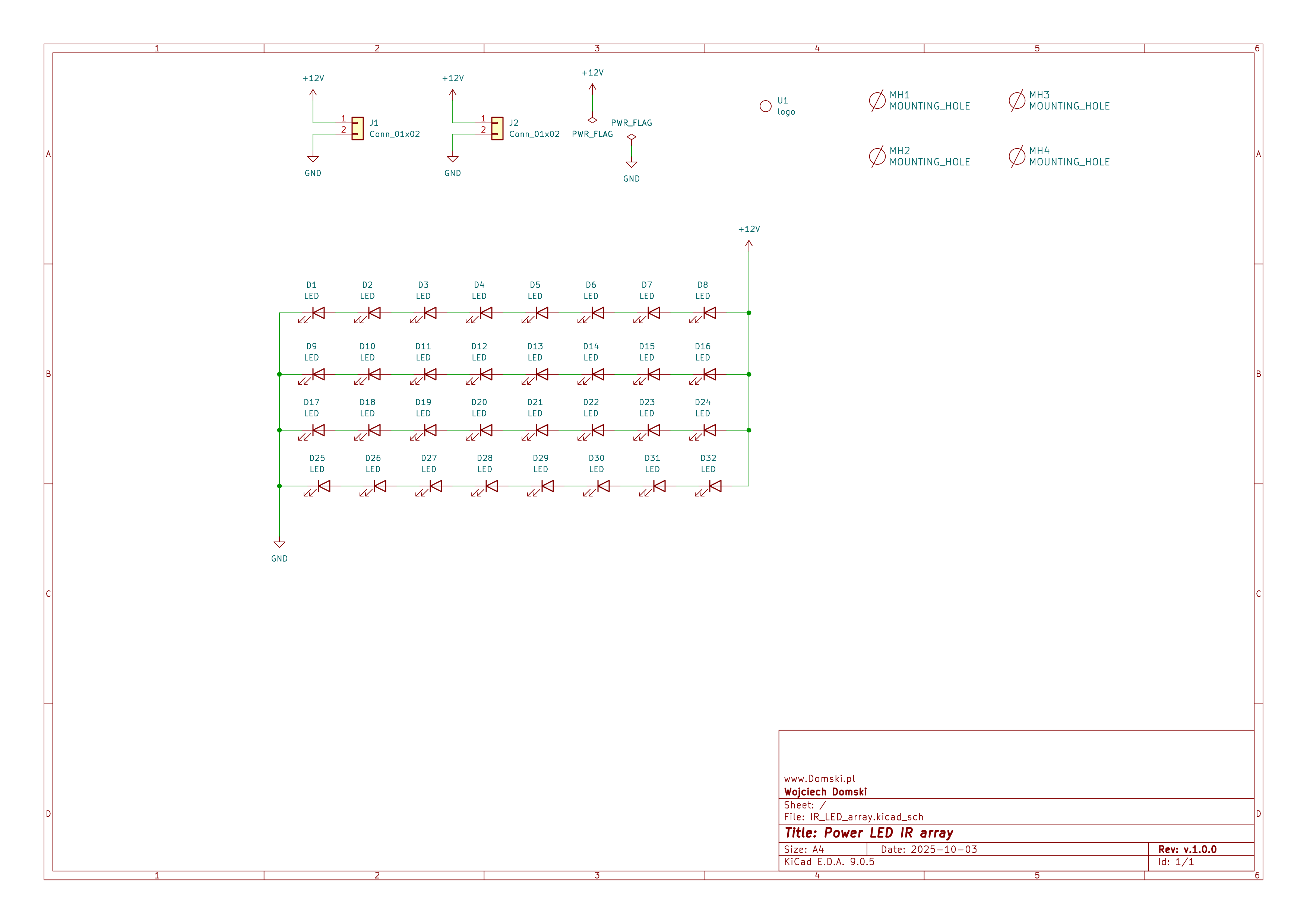
The final module consists of:
- Four strips, each containing seven IR LEDs.
- No additional resistors are required; the 12V input is divided across the LEDs.
- Each LED operates at ~1.714 volts when fully powered.
- When using PWM modulation, one LED per strip can be omitted to increase voltage per LED and increase power output per LED.
Schematic of this module can be found below.
Chaining Multiple Modules: Best Practices
When scaling up your project by chaining multiple modules together, it’s crucial to consider both electrical and mechanical aspects to ensure optimal performance and longevity. Start by ensuring that your power supply can handle the combined load; for instance, if each module consumes approximately 40 watts when fully powered, chaining n modules will require a power supply rated for at least 40n watts. Maintaining consistent voltage across all modules is equally important to avoid uneven brightness or potential damage. Using appropriate gauge wiring can minimize voltage drops over longer distances, ensuring uniform performance.
Thermal management is another critical factor when chaining modules closely together, as this can lead to increased heat buildup. It’s essential to provide adequate spacing between modules to allow for proper heat dissipation. Passive cooling solutions like heatsinks or active cooling methods should be considered if necessary, especially in high-density setups. Additionally, PWM (Pulse Width Modulation) modulation is highly recommended for applications where the module runs continuously. This technique allows for dynamic control of brightness and significantly reduces heat buildup, ensuring longevity and stability.
Mechanical mounting also plays a significant role in the stability and performance of chained modules. Using mounting brackets or spacers can secure multiple modules together while maintaining alignment and ensuring sufficient space for heat dissipation. It’s also important to securely fasten all modules to the surface or enclosure to prevent vibrations, which can be particularly problematic in applications like FPV setups where stability is crucial.
For a practical example, consider setting up a wildlife monitoring system that requires coverage over a large area. You might chain four modules together to achieve a wider field of view. In this scenario, ensure your power supply is rated for at least 160 watts (4 modules * 40 watts each). Additionally, mount the modules with sufficient spacing and use passive cooling if needed to manage heat effectively.
To prevent overheating, PWM (Pulse Width Modulation) is recommended for applications where the module runs continuously. This allows for dynamic control of brightness and reduces heat buildup, ensuring longevity and stability.
Ready Module: Features and Connectivity
The Power IR LED Module is designed for ease of use and scalability:
Key Features:
The module features input and output connectors that allow it to be chained with other modules, enabling extended coverage or higher brightness as needed. When fully powered (with no PWM modulation), the module consumes approximately 40 watts, making it suitable for applications requiring sustained operation.

The module is roughly 91mm x 84mm in size, making it compact enough for various installations while still providing substantial infrared illumination. You may notice that the LED package has a thermal pad on the bottom side, which helps dissipate heat generated during operation. Additionally, there are four M4 mounting holes located at each corner of the PCB, allowing for secure attachment to different surfaces or enclosures.
Hardware Controller and Software
Controlling LED module with PWM driver
The Power IR LED Module can be efficiently controlled using an N-Mosfet. This approach is preferred for its high efficiency and low power loss compared to other switching methods. The N-Mosfet acts as a switch that can turn the IR LED module on or off rapidly, allowing for precise control of the illumination. This is particularly useful when using PWM (Pulse Width Modulation) techniques to vary the brightness of the LEDs without generating excessive heat.


When selecting an N-Mosfet, consider one with a sufficient current rating to handle the load of the IR LED module. For example, if your module draws around 3.5A at 12V (as inferred from the 40W consumption mentioned), you should choose an Mosfet with a drain current (Id) rating higher than this value. Additionally, ensure that the Mosfet has a low Rds(on) (resistance in the on-state) to minimize power dissipation and heat generation.
Here’s a simple example of how you might wire up an N-Mosfet to control the IR LED module:
- Connect the gate of the N-Mosfet to a GPIO pin on your microcontroller or SBC. Use photocoupler, do not connect it directly. Preferably use a module as int the pictures above.
- Connect the VCC (12V) to positive side of the IR LED module.
- Connect the drain of the N-Mosfet to negative side of the IR LED module.
- Connect the source of the N-Mosfet to ground.
When the GPIO pin is set to high, the Mosfet turns on, allowing current to flow from the power supply to the IR LEDs, illuminating them. When the GPIO pin is set to low, the Mosfet turns off, stopping the current and turning off the LEDs.
For applications requiring even higher efficiency or more complex control (like driving multiple modules), consider using an appropriate driver circuit or a dedicated PWM controller that can handle the load more efficiently and provide better thermal management.
Software
For software control, the Power IR LED Module can be seamlessly integrated with a Raspberry Pi single-board computer (SBC) using its GPIO pins. The pigpio daemon provides low-level access to the Raspberry Pi’s GPIO, PWM, and other peripherals, enabling efficient and precise control over the module.
To start using the pigpio library, you first need to ensure that the pigpiod daemon is running on your Raspberry Pi. This can be done by adding the following line to your /etc/rc.local file before the exit 0 line:
pigpiod -s 10 &
Here’s a brief explanation of the command:
pigpiod: The name of the daemon that provides access to the GPIO.-s 10: Sets the sample rate to 10 microseconds. This value is sufficient for most applications and doesn’t put undue strain on the Raspberry Pi’s CPU. Higher sample rates are generally unnecessary unless you’re working with very high-frequency signals.
Once the pigpiod daemon is running, you can use the pigpio Python library to control the GPIO pins and PWM outputs. Below is a minimal example demonstrating how to turn on, off, toggle, and vary the brightness of an IR LED module connected to a GPIO pin using PWM:
Turning On, Off, and Toggling
import pigpio

# Initialize the pigpio client
pi = pigpio.pi()

# Define the GPIO pin connected to the Mosfet's gate (e.g., GPIO 17)
GPIO_PIN = 17

# Set the mode of the GPIO pin to output
pi.set_mode(GPIO_PIN, pigpio.OUTPUT)

# Turn on the LED module
pi.write(GPIO_PIN, 1)  # High signal turns on the Mosfet, illuminating the LEDs

# After some time (e.g., 2 seconds), turn off the LED module
import time
time.sleep(2)
pi.write(GPIO_PIN, 0)  # Low signal turns off the Mosfet, turning off the LEDs

# Toggle the LED module (turn it on if off, or off if on)
pi.write(GPIO_PIN, not pi.read(GPIO_PIN))
PWM Control for Brightness
import pigpio

# Initialize the pigpio client
pi = pigpio.pi()

# Define the GPIO pin connected to the Mosfet's gate (e.g., GPIO 17)
GPIO_PIN = 17

# Set the mode of the GPIO pin to output
pi.set_mode(GPIO_PIN, pigpio.OUTPUT)

# Set PWM frequency and duty cycle for brightness control
frequency = 1000  # Frequency in Hz (e.g., 1 kHz)
duty_cycle = 50   # Duty cycle as a percentage (e.g., 50% brightness)

# Start PWM on the GPIO pin
pi.set_PWM_frequency(GPIO_PIN, frequency)
pi.set_PWM_range(GPIO_PIN, 255)  # Range from 0 to 255 for duty cycle calculation
pi.set_PWM_dutycycle(GPIO_PIN, int(duty_cycle * 255 / 100))

# To stop PWM and turn off the LED module:
pi.set_PWM_dutycycle(GPIO_PIN, 0)
Remember to clean up when you’re done by calling pi.stop(), although this is handled automatically when the script terminates if you’re using a recent version of the pigpio library.
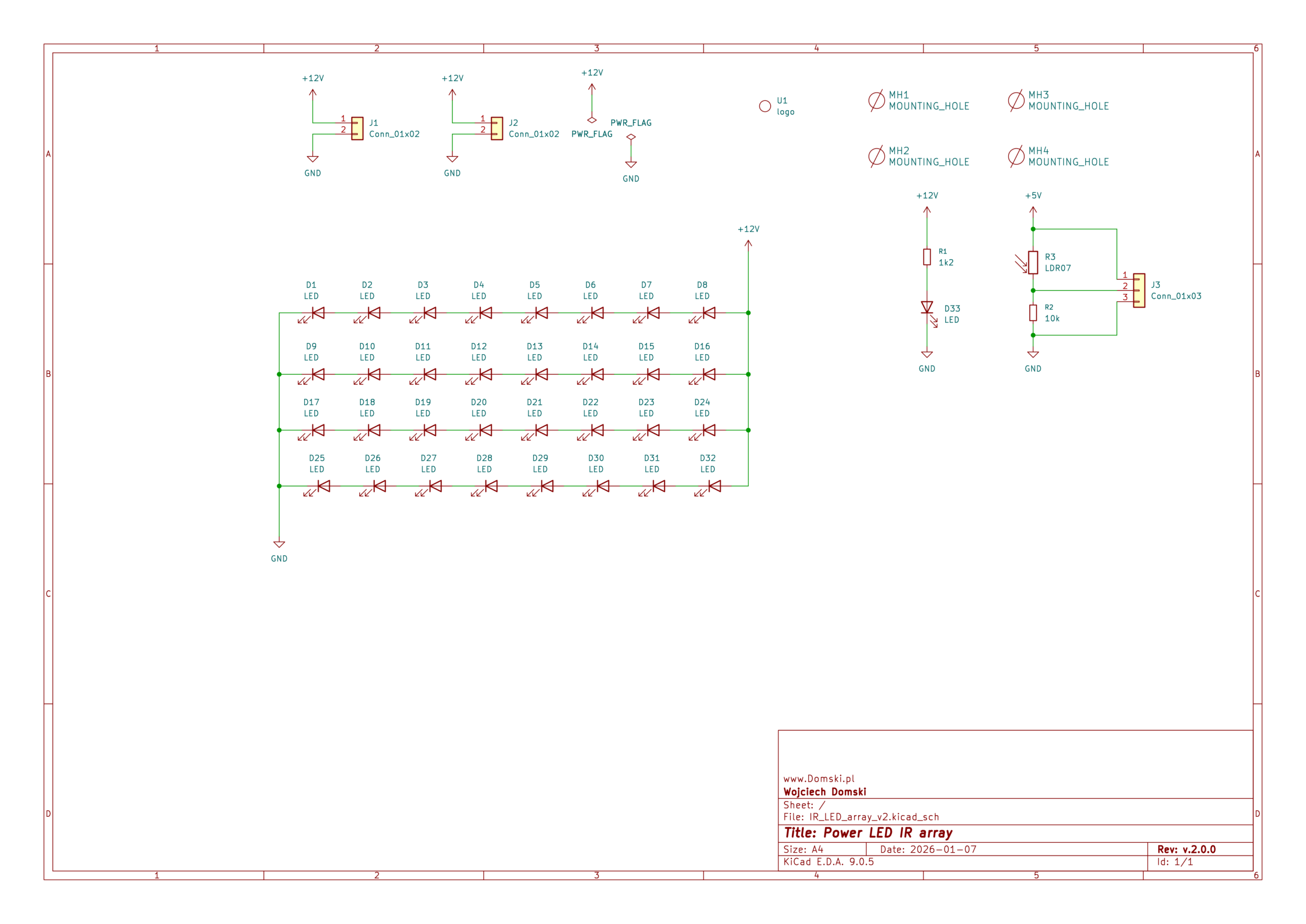
Second Revision: Improvements and Adaptations
After a while I realized that some additional features are needed. I was inspired by another IR LED module which I saw online.

Above image shows a small IR LED module that is dedicated for CCTV applications. It is quite small but it uses 5mm through-hole IR LEDs which are not as powerful as SMD ones that I used in my own design. However, it has two additional features that I found quite useful, so I decided to implement them in the second revision of my Power IR LED Module.
- Status LED: A small visible LED with a resistor indicates whether the module is powered on, providing a quick visual check without relying on infrared detection.
- Photoresistor for Adaptive Operation: The photoresistor measures ambient light levels, allowing the module to activate only in low-light conditions–such as nighttime or overcast weather. This feature is particularly useful for battery-powered applications where energy conservation is critical, ensuring the module operates efficiently without unnecessary power drain.
As it can be seen in the schematic below, these additions enhance the module’s usability and adaptability compared to the first revision.
Practical Applications
The Power IR LED Module is suitable for a wide range of applications, from wildlife monitoring to security systems and FPV (First-Person View, but with a stretch since it is quite big) setups. Its ability to provide infrared illumination without visible light interference makes it ideal for covert observation or situations where subtle lighting is required.
Whether you’re building a custom night vision system, enhancing your drone’s visibility in low-light conditions, or developing an environmental sensor, this module offers the flexibility and performance needed to bring your project to life.
Getting the Project Files
Production Footprint (Gerber Files)
For those interested in manufacturing this module, the production footprint is available for download. This includes all necessary design files to send to a PCB factory, ensuring you can produce high-quality modules tailored to your needs.
Additional files (for Supporters only)
Supporters can access the full project, including:
- Libraries for the IR LED used in the project (which are not commonly found in standard packages).
- Footprint definitions and schematic files.
- Additional code or firmware if applicable.
The files for the first revision can be found here:
Some content is only available for the people who support me. If you would like to access that content consider buying me a coffee ☕. Thank you!
- Power IR LED Module Rev. 1 – project files
IR_LED_array.zip
- Power IR LED Module Rev. 2 – project files
IR_LED_array_v2.zip
Conclusion

The Power IR LED Module is not only a powerful and stealthy solution for projects requiring infrared illumination but also highly efficient when controlled with an N-Mosfet. This hardware approach minimizes power loss and allows for precise control of the module’s brightness using PWM, making it ideal for applications where efficiency and thermal management are critical.
On the software side, integrating this module with a Raspberry Pi single-board computer (SBC) is straightforward using the `pigpio` library. By running the `pigpiod` daemon on boot, you can leverage low-level access to the GPIO pins and PWM outputs for precise control over the IR LEDs. This setup is particularly advantageous for applications requiring real-time adjustments or dynamic brightness control, such as wildlife monitoring systems or adaptive lighting in security setups.
Whether you’re building a custom night vision system, enhancing your drone’s visibility in low-light conditions, or developing an environmental sensor, this module offers the flexibility and efficiency needed to bring your project to life. The ability to chain multiple modules together further extends its utility, allowing for larger coverage areas or increased brightness without overloading a single unit.
I hope you found this blog post informative and inspiring! If you’ve used this module in your projects or have ideas for improvement, share them in the comments below. Your feedback helps me refine my work, so consider supporting me by buying a coffee–it goes a long way in keeping this content ad-free and high-quality.